
Ethernet uses differential signalling to counteract outside interference. The receiving equipment measures the difference signal between the two wires and rejects any component of the signal that is equal but not opposite (i.e. common mode). Any noise signals electrically or magnetically coupled to the data signal affect each conductor equally thus they arrive at the receiver in common mode and are rejected. However, if the noise signal is in close proximity to the signal cables it is inevitable that one of the conductors will lie closer to the noise source than the other so that the induced noise signal is not the same for each conductor. In this instance the common mode rejection is not perfect and some of the noise is transmitted to the receiving equipment. By twisting the conductors together the cables swap between which is nearest to the noise signal once per twist. In this way the noise signal becomes the same in each conductor – common mode rejection reaches nearly 100% and the noise is eliminated. If more than one twisted pair is present in a single data bundle (such as in ethernet cabling) then the conductors of adjacent pairs become a source of noise and can lie alongside each other for some distance partially undoing the effect of common mode rejection afforded by the twisting of the conductors. Therefore, in Reference Ethernet cables we specify that the twist rate or pitch of the conductor pairs should be dissimilar to counteract this spoiling effect and reinforce the inherent common mode rejection characteristics of the differential signalling system.
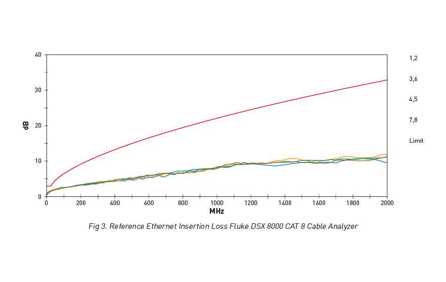
Insertion loss refers to the loss of signal strength at the far end of a line compared to the signal that was introduced into the line. This loss is due to the electrical impedance of the copper cable, the loss of energy through the cable insulation and the impedance caused by the connectors. Insertion loss is usually expressed in decibels dB with a minus sign. Insertion loss increases with distance and frequency. For every 3 dB of loss, the original signal will be half the original power. Due to its accurate characteristic impedance, Reference Ethernet exceeds the requirement for CAT 8 insertion loss by up to 20 dB.
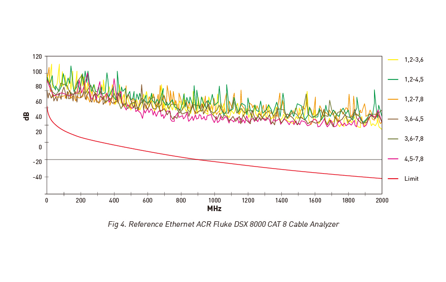
Attenuation-to-Crosstalk ratio (ACR) indicates how much stronger the attenuated signal is than the crosstalk at the destination (receiving) end of a communications circuit. The ACR figure must be at least several decibels for proper performance. If the ACR is not large enough, errors will be frequent. Due to its unique ferrite jacket (which is not available) from any other manufacturer QED Reference Ethernet exhibits an ACR figure up to 25 dB better then the requirement of the CAT 8 standard.
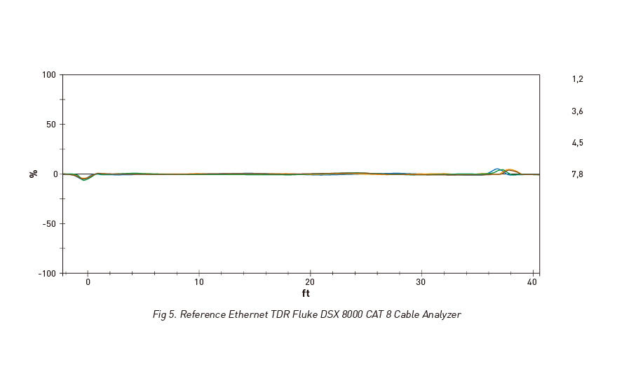
Any impedance mismatch between the cable and the source or sink will cause the signal to be reflected back and forth – this is known as return loss. In Figure 5, the reflected signal is shown by the peaks at the near end and far end of the correctly terminated cable. Ideally, no peaks would be seen, showing that all of the energy has been delivered to the load. In practice it is very difficult to get higher than 90% of the signal delivered to the load, which is why a very small reflection can still be seen in the graph.
Specification
Cable OD (mm)
9 mm
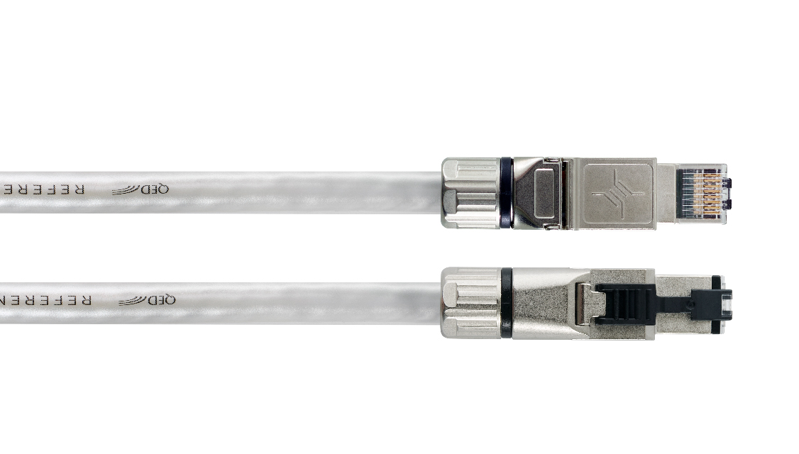
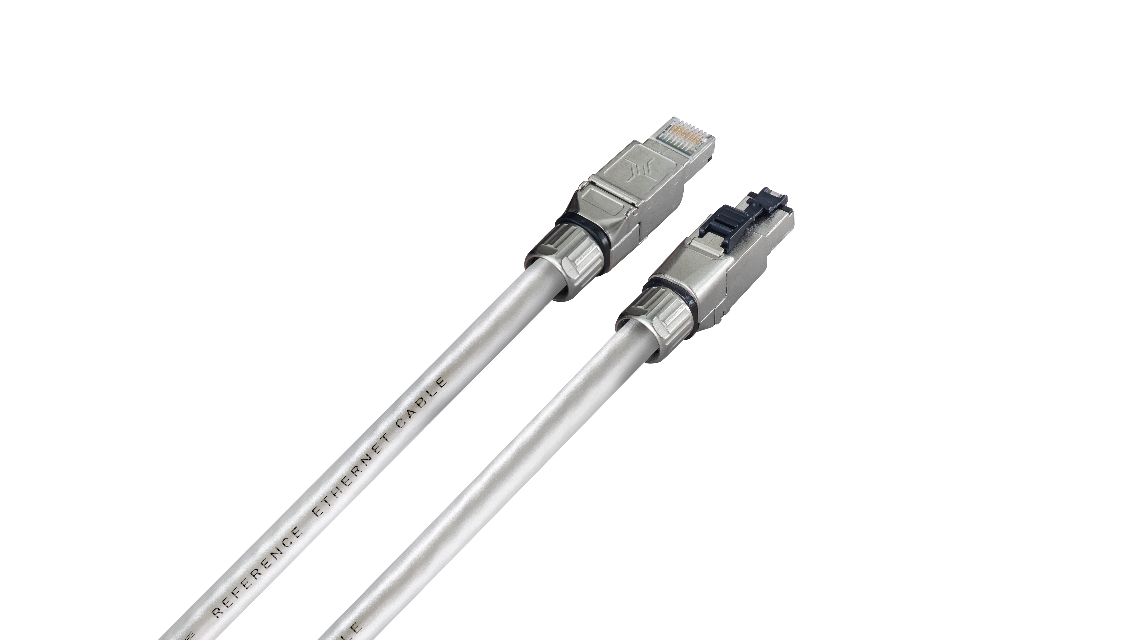
Plugs
Telegärtner Profinet CAT 8
Construction
F/FTP
Conductor size
24AWG
Characteristic Impedance
100 ohm
Patch Cable Category
Class I CAT 8.1
Maximum Bandwidth
2000 MHz
Maximum bit-rate
40 Gb/s
Transmission Characteristics CAT 8 Test Pass Margins*:
Insertion Loss
20 dB
Return Loss
3.2 dB
NEXT
11.3 dB
ACR-F
8.3 dB


Welcome to leave your comments for other users' reference